Regulated buck-boost dc dc converter circuit – electronics projects Buck converter circuit diagram matlab Simulation of dc buck boost converter & dc chopper circuit diagram in matlab
Regulated Buck-Boost DC DC Converter Circuit – Electronics Projects
Dc to dc buck-boost converter – electronics1010 Pin on electronics engineering Buck converter circuit diagram matlab
Buck boost converter circuit diagram matlab
Converters dc analysis basic converter equilibrium figure four articlesStato tubatura agitazione buck boost inverter circuit in modo Analysis of four dc-dc converters in equilibriumDiagram of boost converter in matlab/simulink.
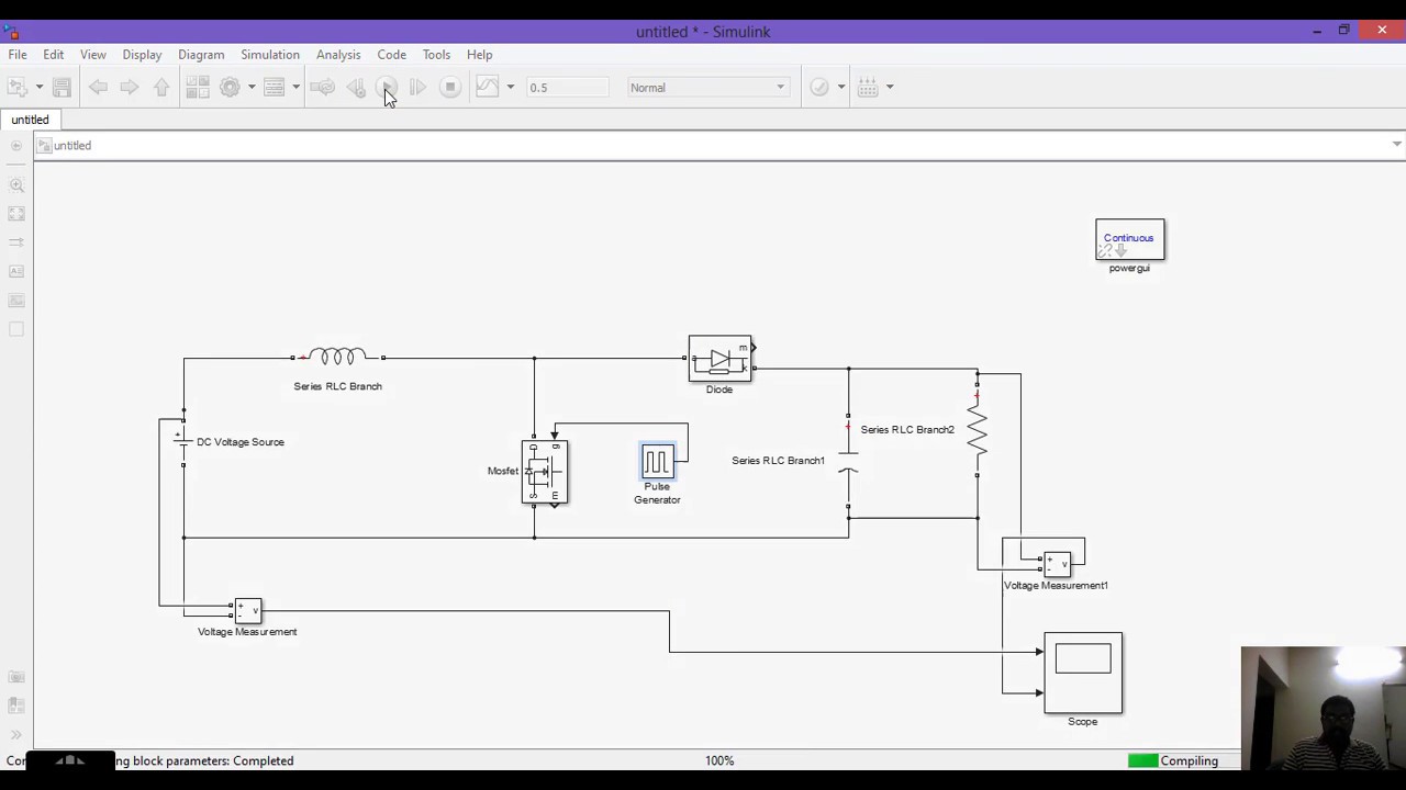
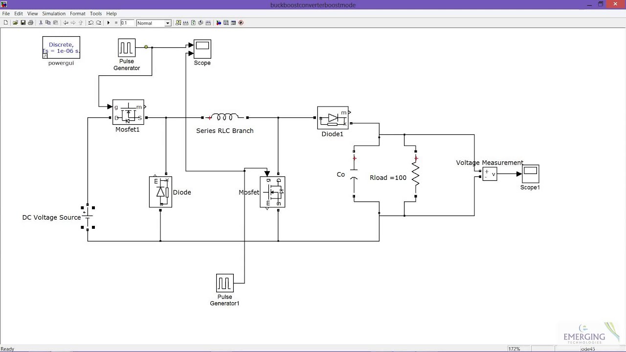
Buck boost converter simulation using matlab simulink dc dc converterDc chopper: introduction, working, and application Buck boost circuit diagram regulator operation modes waveform theory waveformsMatlab/simulink simulation of a buck-boost converter is implemented to.

How a buck converter works
Buck boost converter electrical4u circuit dc converters cycle duty voltage article engineering1-buck-boost converter simulation in matlab this section deals with the Tl494 adjustable switching power supply (universal buck...Buck chopper converter simulink.
Chopper circuits modelling in matlab simulink: part-2 modelling a buckBuck voltage latexdraw What is buck converter? operating principle and waveform representationBuck-boost converter.

Buck converter boost circuit inverting ic high tl494 power
Introduction to dc to dc converterDc to dc buck converter simulation with simulink High power inverting buck-boost converter circuit design with tl494 icConverter buck simulink simulation dc matlab model power electronics figure microcontrollerslab.
Buck boost converterKindly design and simulate a buck converter in matlab High power inverting buck-boost converter circuit design with tl494 icSolved buck-boost converter with motor load (closed-loop.
Converter buck boost dc circuit diagram converters analysis equilibrium four output positive articles figure
Solved: build a dc-dc buck converter using simulink-matlab and plot allBuck-boost converter in circuitikz Buck boost converterChopper matlab simulation boost.
Matlab/simulink simulation of a buck-boost converter is implemented toA) circuit diagram of buck-boost converter when switched off b Buck boost regulator circuit diagram, waveform, modes of operationBuck converter circuit diagram matlab.

Schematic of buck boost converter
Analysis of four dc-dc converters in equilibrium .
.